OBJECTIVES:
Provision of access to the following infrastructure(s):
TU/e ABLWT
Name of the infrastructure and its installations:
TU/e Atmospheric Boundary Layer Wind Tunnel (ABLWT)
Location (town, country) of the infrastructure:
Horsten 80, 5612 AZ Eindhoven, Netherlands
Web site address:
https://www.tue.nl/en/research/research-labs/wind-tunnel/
https://www.tue.nl/en/our-university/about-the-university/support-services/equipment-and-prototype-center/
Reference contact for potential TA user groups
Stefanie Gillmeier – s.g.gillmeier@tue.nl
Bert Blocken – b.j.e.blocken@tue.nl
DESCRIPTION OF THE INFRASTRUCTURE:
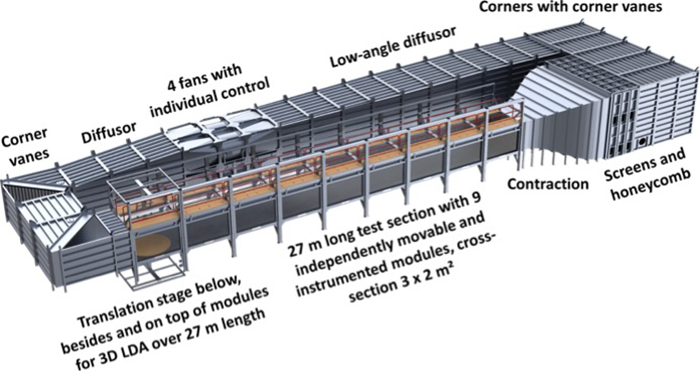
The wind tunnel is a closed-loop circuit atmospheric boundary layer wind tunnel (ABLWT) with a total length of 46 m and a test section length of 27 m. The test section is 3 m wide and 2 m high (Figure 1). The turbulence level at the exit of the contraction is about 0.3%. Low-turbulence measurements are performed in the front part of the test section (near the contraction), while high-turbulence (atmospheric) measurements are performed towards the rear part of the test section. The test section consists of nine modules, each of which 3 m in length and width. The first three modules can be taken out and replaced by a hydraulically operated horizontal platform for open section testing of larger obstacles. Wind catchers can be installed for the open section tests. The wind tunnel is instrumented with two high-accuracy turning tables of 2 m in diameter at the 2nd module for low-turbulence measurements and at the 8th module for atmospheric measurements.
Each module has a glass side wall and a partially glass ceiling to provide visual and laser access. A glass floor is available at the rear turntable location. The glass side wall of every module can slide upwards to create physical access to the inside of this module. The roof has partial openings to reduce longitudinal pressure gradients. Eight Pitot-static tubes are mounted on the side of every module to monitor the pressure along the whole test section (27 m).
The unique character of this facility is its exceptionally long test section (27 m) together with its flexibility to be operational in closed as well as open sections for low and high turbulence flows. In the closed section, the long test section of this facility allows it to reproduce neutral ABL winds for different terrain categories in accordance with the International Standard Codes in civil engineering. For this purpose, L-shaped metal squared elements of different sizes (0.02 m – 0.08 m) and vortex generators (i.e., spires) are combined in order to generate ABL flow at different geometric scales.
Another unique feature is the large degree of visual access to the test section with large side and ceiling windows along the test section. A camera system records all measurements from a side and top view.
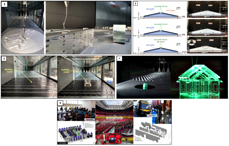
The measurement equipment is partially equipment that was purchased at commercial companies and equipment that was designed and fabricated in-house in collaboration between the wind tunnel team and the university’s Equipment Prototype Center (EPC). The commercially purchased measurement equipment is composed of a programmable Laser-Doppler Anemometer (LDA) that can be translated along the entire test section length of 27 m, and can be placed on top, besides or below the test section. The LDA provides a non-intrusive way to obtain time-series of point velocity measurements in complex flow fields. In addition, a qualitative flow visualization can be carried out by means of smoke machines and visualization lasers that can be placed at any position, when operating in open and closed test sections. A three-axis traverse system with a Cobra j-probe mount can translate along the entire length of the wind tunnel’s test section and allows the positioning of the measurement equipment at any location inside the wind tunnel to measure the three-components of the wind speed. Pitot-static tubes are installed to monitor the approaching reference wind flow. Eight Pitot-static tubes are mounted on the side of every module to monitor the pressure along the whole test section (27 m). A Scanivalve pressure measurement system with 256 pressure transducers that can measure the pressure at 256 locations simultaneously with a frequency of up to 800 Hz is used to estimate wind loads on a large variety of scaled models (as buildings, solar panels, etc.). Pollutant dispersion measurements are carried out with a Fast – Flame Ionization Detector (Fast – FID) from Cambustion.
The in-house designed equipment consists of a range of high-precision force sensors (accuracy of about 0.001%) designed and manufactured by the EPC. The range of force sensors stretches from 20 N to 100 N and can capture forces in one and two directions, respectively. In addition, four commercial 3-axis-force sensors are available with a horizontal range of 0.5 kN and a vertical range of 2.5 kN for tests on large and heavy objects.
A unique feature resulting from the collaboration between wind tunnel and EPC is that, depending on the user’s requirements, new measurement equipment or specific models with integrated sensors can be designed and developed internally by EPC.


